×
A wheelchair frame has to do something that many lightweight structures do not: remain dependable through thousands of repeated transfers, pushes, folds, impacts, surface changes and daily handling cycles while staying comfortable to transport and easy to control. That combination makes wheelchair design a demanding engineering problem rather than a simple exercise in removing metal.
Carbon fiber has become an important material in this discussion because it allows designers to place reinforcement where the structure needs it most. A properly designed carbon fiber wheelchair frame can combine low structural mass, controlled stiffness, corrosion resistance and a highly integrated appearance. However, the material is not automatically better in every design. Fiber orientation, joint architecture, impact protection, surface finish, repairability and user-specific fit all matter.
For manufacturers and product developers, the most useful question is not “Is carbon fiber lighter?” It is: Which wheelchair components benefit from composite construction, and how should those components be designed, manufactured and validated?
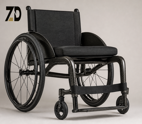
Traditional wheelchair frames often use aluminum, steel or titanium because these materials are familiar, repairable and easy to join. Carbon fiber introduces a different design logic. Its properties are directional, which means the designer can align reinforcement with the main load paths instead of relying on the same material thickness in every direction.
This can create several engineering advantages:
These advantages should be evaluated together with the application. A rigid active-mobility chair, a folding transport chair, a sports chair and a rehabilitation device do not experience the same loads or user expectations. The best material architecture for one may be unsuitable for another.
The phrase “carbon fiber wheelchair” can describe a complete frame or only selected components. In practice, composite material may appear in several different areas.
The main frame carries the largest share of the structural load. Depending on the chair architecture, these members may be tubes, curved shells, molded side frames or a combination of composite panels and metallic interfaces.
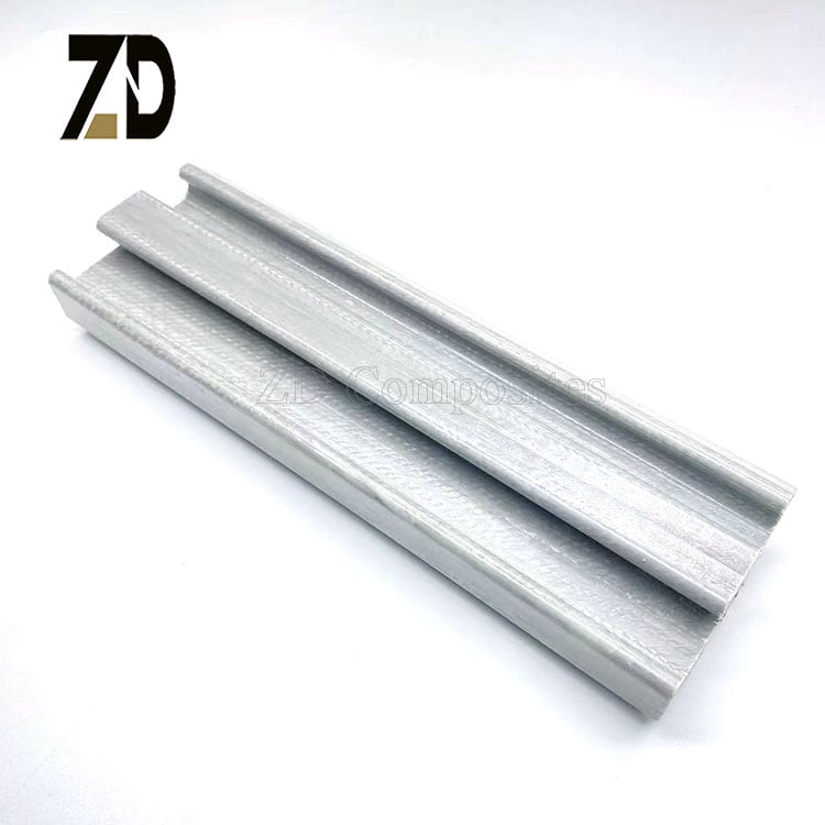
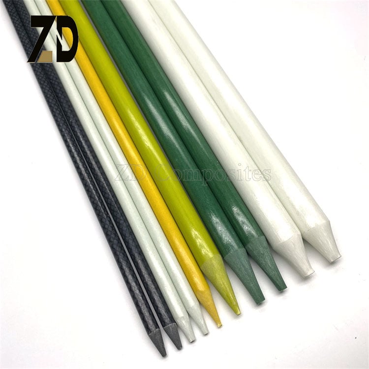
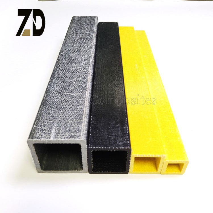
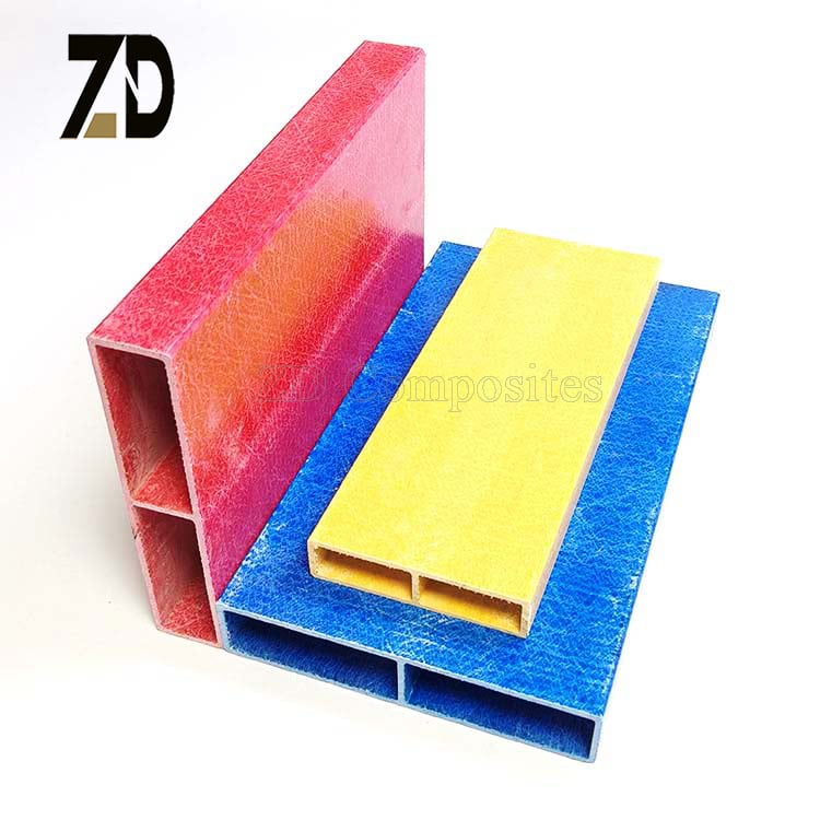
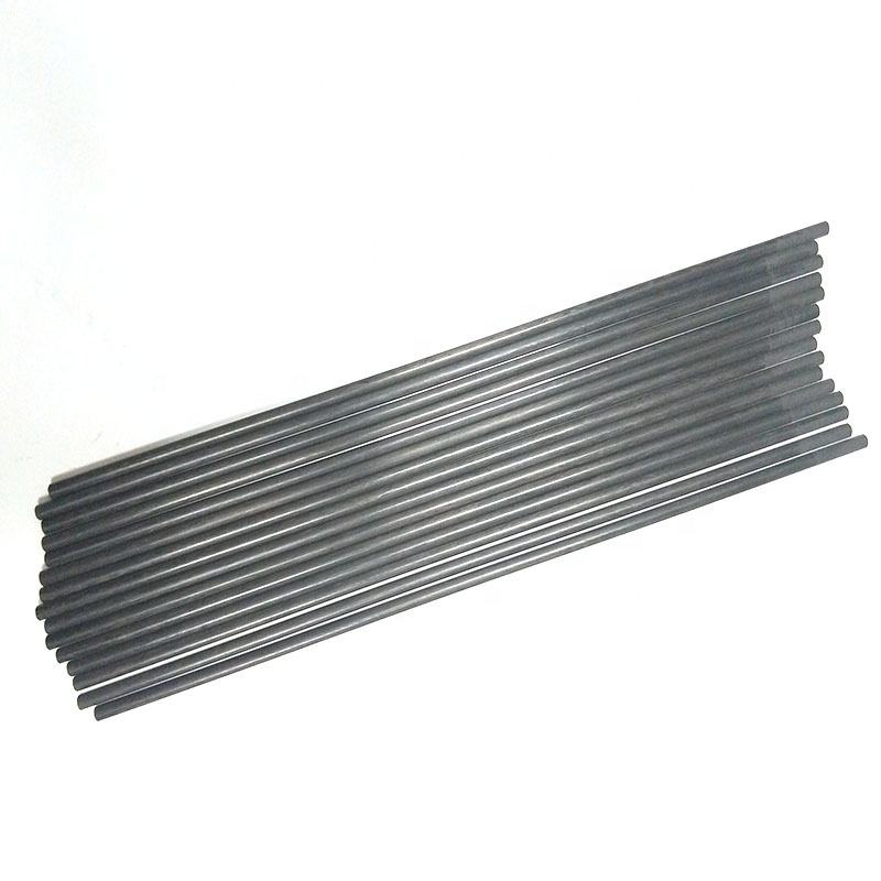
Round carbon fiber tubes are useful where the design requires continuous bending stiffness, smooth load transfer and a clean tubular appearance. Rectangular or custom profiles can offer wider mounting faces for brackets, upholstery supports, side guards or folding hardware. A pultruded profile may be appropriate for a long, constant cross-section, while a molded or roll-wrapped structure may be better when the geometry includes curves, variable thickness or integrated joints.
The frame must be designed as a complete load path. Increasing the stiffness of one tube does not automatically improve the whole wheelchair if the adjacent joint, axle mount or fastener interface remains flexible.
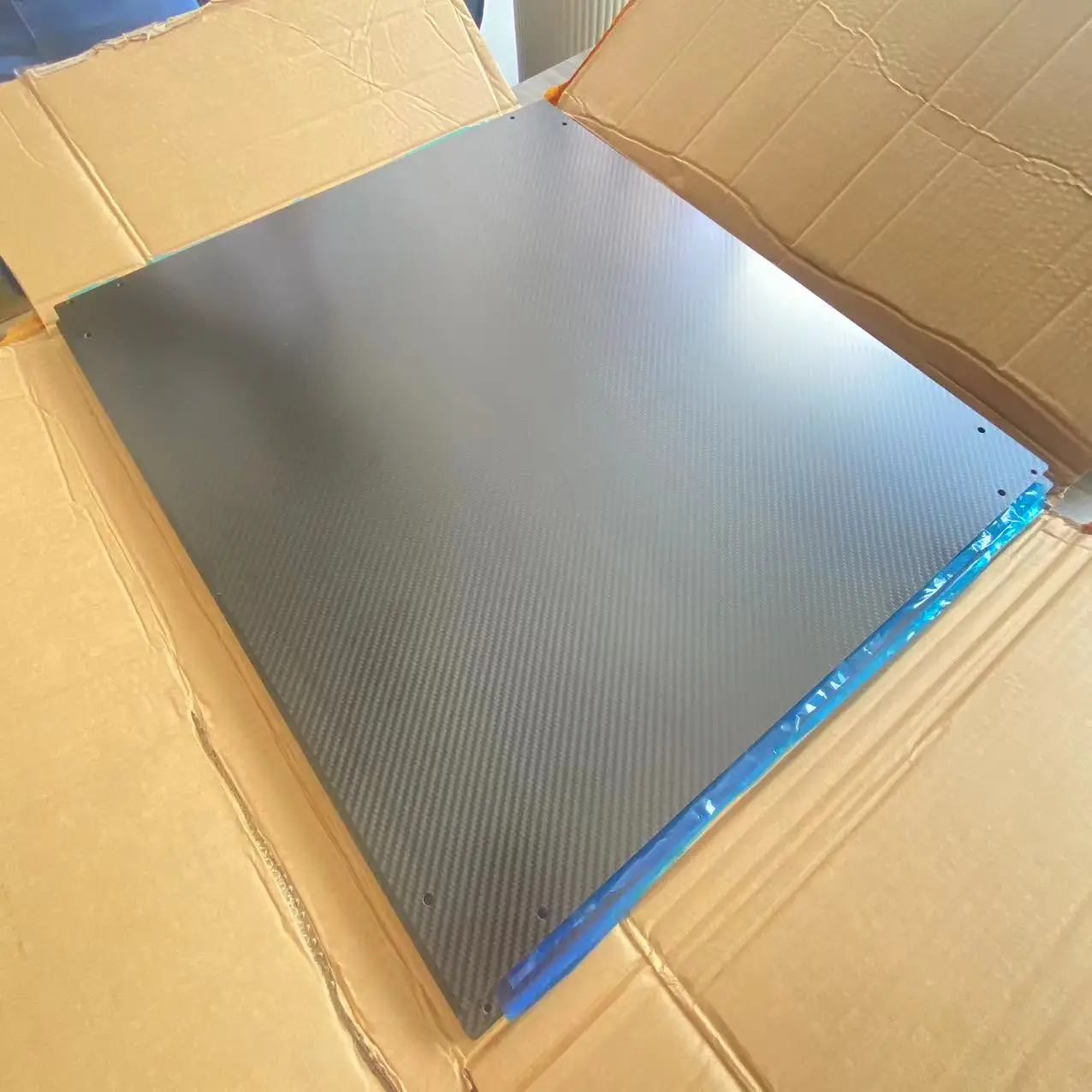
Side guards, seat rails and back-support components are often ideal candidates for carbon fiber because they benefit from a thin, clean geometry and do not always require complex multi-axis joints. A carbon fiber plate can be CNC machined into a custom shape with cut-outs, mounting holes and edge finishing.
For a production program, the supplier should confirm fiber orientation, laminate thickness, hole-edge reinforcement and the way fasteners are isolated from the laminate. Carbon fiber components should not be treated exactly like aluminum plates during drilling and assembly. Poor hole preparation or over-tightened fasteners can create local damage even when the overall part looks strong.
Wheel mounts and axle interfaces require careful engineering because they transfer concentrated loads into the frame. These areas may use aluminum or stainless-steel inserts bonded or mechanically secured within a carbon fiber structure. The metallic interface provides threads, bearing surfaces or replaceable attachment points, while the composite structure carries the distributed load around the joint.
This hybrid approach is common in high-performance composite design. It avoids forcing carbon laminate to perform a job that a machined metal insert can perform more reliably, especially when the part must be removed, adjusted or serviced repeatedly.
A folding wheelchair creates a special challenge: the frame must be light and stiff during use but also accommodate controlled movement at hinges or cross-brace joints. Composite tubes and plates may reduce mass in the moving structure, but hinges, pivot pins, bushings and locking components still require robust interfaces.
The design should account for clearances, pinch points, repeated opening and closing, fastener preload and inspection access. Carbon fiber is most valuable when it is integrated with a well-designed mechanical system, not when it is used as a direct replacement for every metal component.
Aluminum remains a strong reference material for wheelchair manufacturing. It is relatively accessible, easy to machine and familiar to many repair networks. Carbon fiber becomes attractive when the project places a higher value on mass reduction, stiffness distribution, integrated styling or specialized customization.
| Design consideration | Carbon fiber composite | Aluminum alloy |
|---|---|---|
| Density | Low | Moderate |
| Directional stiffness | Tunable through fiber lay-up | More uniform and isotropic |
| Corrosion behavior | Composite does not rust; interfaces need protection | Requires suitable alloy and finish |
| Geometry | Strong for integrated or curved structures | Strong for machined and extruded parts |
| Repair approach | Requires composite-specific assessment | Often easier to straighten or replace |
| Joint design | Needs inserts, bonded interfaces or clamps | Threads and fasteners can be machined directly |
| Production economics | Attractive for specialized or repeat production | Often economical for standard and low-volume parts |
| Surface appearance | Woven, UD or painted composite finish | Anodized, painted or machined metal finish |
The table is not a universal ranking. It is a reminder that material selection should follow the product architecture, production volume, service model and user requirements.
Different wheelchair parts require different processes. Selecting a process based only on the phrase “carbon fiber” can lead to unnecessary tooling cost or an unsuitable structure.
Pultrusion is a continuous process that pulls impregnated reinforcement through a heated die to create a constant cross-section. It is well suited to long, straight carbon fiber tubes, rods, rectangular tubes and other profiles.
For wheelchair projects, pultruded carbon fiber profiles may be considered for frame rails, support members, push handles or other components where the cross-section remains constant over the part length. The process can provide repeatable geometry and efficient production for recurring orders. Ends, holes and interfaces can then be machined or fitted with inserts in secondary operations.
Roll-wrapped construction can provide more flexibility in fiber orientation and tube architecture. It is useful when the designer needs specific winding angles, a custom wall build-up or a tube diameter that does not fit a standard pultrusion die.
This process may be considered for curved or stiffness-tuned tubular members, but the final choice depends on geometry, quantities, loading direction and surface requirements.
Compression molding can create more complex shells, brackets and frame sections with variable geometry. It becomes relevant when the part needs curved transitions, integrated ribs, mounting bosses or a controlled external shape.
Tooling investment is an important consideration. Compression molding may be appropriate for a stable design and repeat production, while CNC machining from carbon fiber plate or a simpler tube-and-insert assembly may be more suitable during prototyping.
Carbon fiber plates, tubes and molded parts often need secondary machining before assembly. Typical operations include cutting, drilling, trimming, edge finishing and the preparation of openings for inserts or fasteners.
Machining parameters should be selected to reduce delamination, fiber breakout and edge damage. The finished part should be checked not only for external dimensions but also for hole quality, edge condition, surface protection and interface alignment.
The strongest material can still produce a weak assembly if the interface is poorly designed. Wheelchair components include many concentrated load locations: axles, casters, wheel mounts, folding pivots, seat supports, footrests and backrest hinges.
A practical design review should consider:
These points are especially important for OEM buyers who plan to integrate a carbon fiber component into an existing mobility platform.
The visual appeal of a carbon fiber wheelchair often comes from the material surface itself, but appearance should not replace engineering requirements. A glossy woven finish may be suitable for a visible frame, while a matte coating may reduce glare and make routine handling marks less noticeable.
The finish specification should address:
Carbon fiber is not automatically scratch-proof or impact-proof. A real product specification should define where cosmetic quality matters and where a protective coating or replaceable cover is more appropriate.
A capable supplier should contribute more than a material quotation. The supplier should be able to review the load path, manufacturing route, joint details and inspection requirements before production begins.
For an initial review, an OEM buyer should prepare:
If the design is still at concept stage, photographs, sketches and a description of the intended use can start the discussion. However, final manufacturing recommendations should be based on approved drawings and a defined validation plan.
A carbon fiber wheelchair component should be validated as part of the complete assembly. A visual inspection of the composite surface is not enough to establish suitability for service.
Depending on the project, the validation plan may include dimensional inspection, fit checks, repeated folding cycles, static load testing, impact evaluation, fastener-retention checks, environmental exposure and user-specific functional trials. The exact test method should be established by the product owner and relevant technical or regulatory requirements.
For mobility products, validation should also consider practical daily events: loading the chair into a vehicle, contact with door frames, uneven ground, repeated transfers, storage impacts and cleaning. These conditions often reveal interface or service issues that a simple bench test does not show.
The next generation of carbon fiber wheelchair design is likely to focus less on replacing every metal part and more on combining materials intelligently. Carbon fiber can provide lightweight structural members, while aluminum, stainless steel, polymers and elastomers handle threads, wear surfaces, adjustment points and impact protection.
Digital design tools can help engineers map stiffness and mass distribution before tooling is committed. CNC-machined prototypes make it possible to test fit and ergonomics early. Once the design is stable, pultruded profiles, molded components or dedicated tooling can support a more efficient production route.
This integrated approach creates a realistic path for custom mobility products: start with the user and the load case, select the appropriate composite architecture, use metal only where it adds service value, and validate the complete assembly before scaling production.
A carbon fiber wheelchair is not defined by a black surface or a lower number on a scale. Its value comes from how the fiber architecture, frame geometry, interfaces, adjustment system and manufacturing process work together.
For wheelchair manufacturers, rehabilitation-product developers and mobility-equipment brands, carbon fiber can open new possibilities in lightweight frame design, custom fit and product integration. The most successful projects begin with a clear engineering brief rather than a material slogan.
If you are developing a carbon fiber wheelchair frame, tube, plate, side guard, axle interface or custom mobility component, send us your drawings, target application and production requirements. Our engineering team can review the load path, compare pultrusion, roll-wrapping, molding and CNC processing, and recommend a manufacturing route suited to your project stage.
Request a carbon fiber mobility component review: provide the part geometry, user load case, adjustment requirements, surface expectations and estimated quantity for an OEM/ODM discussion.
Carbon fiber wheelchair frame and lightweight mobility structureCarbon fiber wheelchair frame joint with axle mount and composite tube interfaceCarbon fiber wheelchair designed for everyday urban mobility and outdoor accessCarbon fiber wheelchair component manufacturing with composite lay-up and CNC finishingNo. Suitability depends on the frame architecture, load case, impact environment, adjustment system, service requirements and applicable product standards. Carbon fiber is one option within a complete engineering design.
No. A frame may combine pultruded or roll-wrapped tubes, carbon fiber plates, molded sections, aluminum inserts and mechanical fasteners. The best combination depends on geometry and production volume.
Yes. Frame members, side guards, seat supports, plates, brackets and interface components can be developed around approved drawings, samples or a defined engineering brief.
Provide drawings or CAD files, dimensions, material preference, surface finish, load case, interfaces, prototype quantity and estimated production volume. If the design is preliminary, photos or sketches can start the review.
No. Surface appearance does not prove structural performance. Safety depends on the full design, manufacturing quality, joints, validation testing and compliance requirements.
Keywords: carbon fiber wheelchair, carbon fiber wheelchair frame, carbon fiber wheelchair parts, lightweight wheelchair frame, custom carbon fiber mobility components, carbon fiber composite mobility design
 Hot News
2026-10-17
2026-10-12
2026-09-25
2026-09-08
2026-09-05
2026-08-10

 EN